



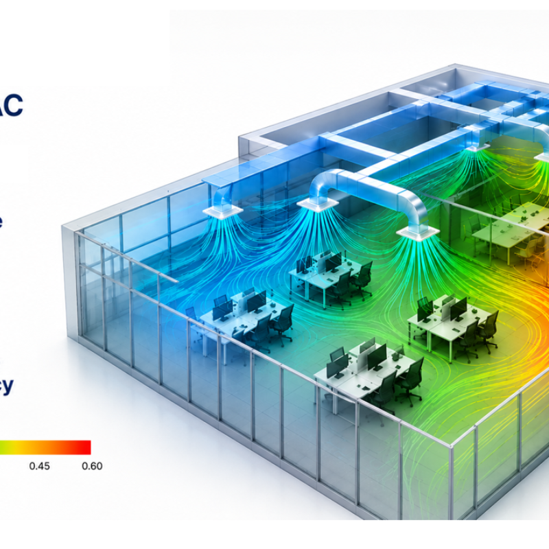
Use of CFD in Modern HVAC Simulation
Complex HVAC systems consisting of convectors, air grilles and other climate control systems are difficult to evaluate on their performance throughout entire rooms and buildings. CFD simulations offer insight into the strengths and weaknesses of the HVAC system by analysing the thermal comfort at each location in a room.
On request of clients, we assessed the thermal comfort for various HVAC systems in both summer and winter conditions by evaluating typical comfort parameters such as
- draught rate (DR)
- PMV/PPD
- Temperature and operational temperature
- Air flow velocity
- air residence time (also known as age of air)
- and more.
How we simulated it
We used a steady state RANS CFD simulation with the SST k-ω turbulence model to capture the short-duration airflow and mixing effects. In addition the energy transport equation and radiation model (discrete ordinates method) are implemented.
The setup includes:
- Detailed modelling of the HVAC systems
- Effects of internal heat production (e.g. people, lighting and devices)
- Infiltration at the windows
- External head loads (e.g. solar radiation and environmental temperatures)
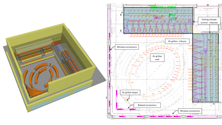
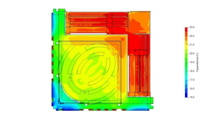
In this case the HVAC consists of multiple air supply grilles, convectors adjacent to windows and a climate control ceiling. The HVAC system is tested for a winter scenario where the external environment is at -8 °C. Results of the operational temperature show
- Optimal working of the climate control ceiling above the tribunes
- Good levels of temperature regulated by air supply grilles throughout the central oval.
- Cold air infiltration at the windows, based on which the client adjusted the convectors to minimize the effects.
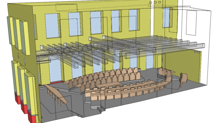
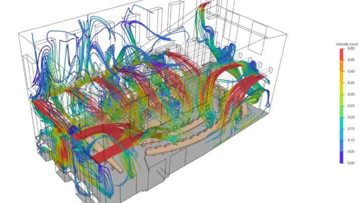
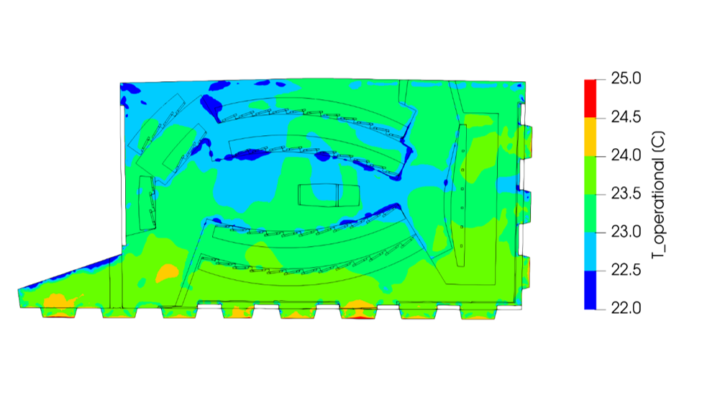
In this second case the HVAC system consists of multiple air supply grilles and convector wells at the windows. One of the CFD simulations for this case was performed to test the HVAC system on the cooling capacity during a summer scenario. The results of the simulation helped
- Show high velocities caused by the interaction of flows originating from different air supply grilles
- Identify in which locations the HVAC system can cool the room sufficiently, and where higher temperatures can arise.
Why this matters
The CFD simulation results provide an insight into the workings of the HVAC system before it is installed. In this way problems can more easily be identified allowing for swift changes to the design.
For case 1, intermediate results had shown that the convectors in the original design failed to counteract the cold fall from the windows. To account for this, the client adjusted the convectors accordingly to improve the thermal comfort in the oval region.
For case 2, intermediate results indicated high flow velocities throughout the entire room. To resolve this issue, the client has removed multiple air supply grilles from the HVAC system where the flows merge and accelerate, resulting in less draught and an improved thermal comfort.